


Frequently asked questions (FAQ)
Can a control valve be mounted with actuator in horizontal position?
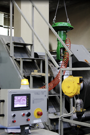
Yes. Parcol control valves can work in any orientation, however the preferred installation is with actuator in vertical position. This will prevent side-loading of the internal components, the valve will have a much longer service life and maintenance easier. However a special attention must be paid to the following aspects whenever a horizontal installation is provided:
- steam jacketing, if provided, must grant a good condensate drain; this means that steam jacketing outlet connection shall be in the lowest possible position
- accessories such as filter airset, solenoid valves, etc., must be installed in upright position.
The request of installation with actuator in horizontal position must always and clearly be indicated to the manufacturer of the control valve.
Valves on Cryogenic service (-100°C and below) must not be installed with actuator in horizontal position (see FAQ on this issue)
How to define seat leakage class for control valves?
A control valve's ability to shut off has to do with many factors. Seat material, actuator thrust, pressure drop, and the type plug (balanced or unbalanced) can all play a part in how well a particular control valve shuts off. Seat Leakage Classifications There are actually six different seat leakage classifications as defined by IEC 60534-4 std or ANSI/FCI 70.2. They commonly range from CLASS IV to CLASS Vl CLASS IV is also known as metal to metal. It is the kind of leakage rate you can expect from a valve with a metal plug and metal seat. CLASS Vl is known as a soft seat classification. Soft Seat Valves are those where either the plug or seat or both are made from some kind of composition material such as Teflon or similar.
What is the difference between flashing and cavitation?
Cavitation is a condition that occurs in liquid flow where the internal pressure of the liquid, at some point falls below the vapour pressure and vapour bubbles formation takes place. After this point the pressure rises above the vapour pressure again and during this pressure recover stage (recall also the concept of FL) the bubbles collapse, and cavitation takes place. Flashing is a condition that occurs with liquid flow where the pressure falls below the vapour pressure (same as cavitation) and remains below it. There are then two phases flowing (i.e. liquid and vapour) downstream and no collapsing of bubbles takes place.
How can cavitation damage be contained?
Several methods exist for treating cavitation in control valves. The first is to select valves with high values of FL (recovery factor) eliminating cavitation (please refer to Limiphon and Varistep bulletins for more information on these option). The second is to ensure that the plug and seat are made of a material that can resist the damage (e.g. stellite hard facing). The third is to control where the bubbles collapse and keep this away from vulnerable components (for instance close to internal surface of valve body or pipe).
Why a control valve on Cryogenic Service cannot be mounted with actuator in horizontal position?
The working principle of the extended bonnet (named "cold box") used in cryogenic service (below -100°C) is based on the principle that portion of LNG which evaporates and stagnates in the upper portion of the bonnet has a function of thermal insulation between the process fluid and the gland packing. In this way ice formation on valve stem is avoided. To grant this benefit the stem/actuator axis must be in upright position. Therefore valves installed on a vertical pipe (with the actuator in horizontal position) cannot work properly.
What is the difference between "Rangeability" and "Turn-down" in a steam desuperheating system ?
The term "rangeability" normally refers to a mechanical concept applied to a single throttling device.
F.i. for a control valve the "rangeability" is ratio between the max flow (or Cv) and the minimum controllable flow (or Cv). When two of such devices are associated, in our case on water and steam line, the minimum and maximum controllable flow of the system as a whole could be affected by other factors. Typically in steam conditioning systems some prescriptions in terms of steam velocity are required for a good performance (not lower than..) and therefore the working range of the system may be lower than the "rangeability" of each individual device. Therefore the ratio between maximum and minimum controllable flow of the whole system is what we call "turn down".
Why the orifices of Pressure Safety Valves indicated by manufacturers are with non-API dimensions, even though designation is as per API ?
The API 520 recommends to do a preliminary sizing of safety valves with the proposed flow-coefficients 0.975 for gas/vapour, 0.65 for liquids and the effective orifice areas written in API 526 (D to T). So, the API uses effective discharge-coefficients and effective areas. At the end this standarizes the flow capacity and allows the engineers to select valve sizes at early stages. API Valves (range 1" x D x 2" to 8" x T x 10") which are approved by the various National Boards must prove that the capacities are achieved.
Parcol do 100% comply to API 520/526 with pressure safety valve series 3-5400. Beside meeting all other design criteria, Parcol valves achieve the 'standardized' flow as minimum. It must be understood that the effective coefficient of discharge for gas/vapours of 0.975 cannot be achieved in reality, so the actual coefficients of discharge is generally less. This is not only the matter for Parcol rather than for all manufacturers valves. To meet the API standardized flow then the actual area must be larger than the effective orifice areas given in the API.
Note that after preliminary sizing the API 520 recommends to verify the calculation with the actual figures provided by the manufacturer. Please see API 520, para. 3.2 for further information. Exactly this is what you find on Parcol sizing software print-out, where the calculation of the actual flow as verification of the orifice selection is shown. The certified capacity of API valves calculated with the actual figures must be always equal or larger than calculated with the effective values.


www.koso.com | www.koso.co.in | www.kentintrol.com | www.koso.com.cn | www.rexa.com | www.kosokor.co.kr | www.hammeldahl.com